Tranz4mr’s KW Page


Tranz4mr’s KW Page


KW Rebuild
KW’s evolved over the years from layered cores to riveted Type R cores. Like ZW’s, KW type R’s tend to be very quiet if the core is assembled correctly. KW’s with layered cores tend to have varying amounts of 60 Hz hum. Other things that changed were the circuit breakers. Common problems with KW’s are worn rollers, broken or loose terminals, bad whistle rectifier discs, broken Bakelite studs used to stop the whistle switches and bad solder joints where they attach to the whistle rectifier bracket or to the circuit breaker.
1. Verify that the Power Cord is unplugged!
2. Remove the Red Lens Cover.
3. Remove the Bulb from the Top Cover.
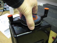
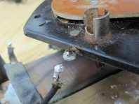
4. Remove the top “B” handle by grabbing it at the center and pulling straight up while gently rocking side to side. Photo #1
5. Remove the aluminum disc and the second “A” handle by lifting up. Photo #2 & #3.
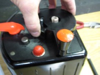
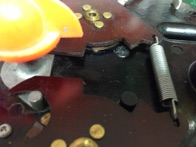
6. Remove the orange Whistle Lever by pulling straight up.
7. Remove the 4 Phillips Head Screws that hold the Cover on.
Photo #4
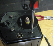
8. Remove the KW top cover.
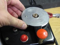
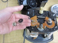
9. Remove the 2 Direction Buttons, Springs, black Discs and black Pegs. Photo #5
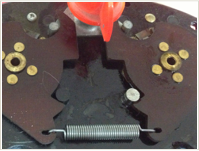
1. Remove the Spring connecting the A & B Whistle switches.
Photo #6
1. In order to remove the top plate several wires need to be unsoldered. Unsolder the small wire going to the bulb socket. It goes to the Disc under the bulb. Push the wire and disc up out of the socket then unsolder the Disc and remove the Spring under it.
Photo #7.
2. Unsolder the 2 Black and Yellow wires shown in Photo #8 on the top plate left edge.
3. Unsolder the Black wire shown in Photo #9 on the top plate right edge on the tab next to the Light Socket.
4. There are 3 wires attached to the Circuit Breaker. Unsolder all 3. Photo #10. The Circuit Breaker shown is the older style.
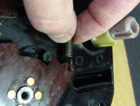
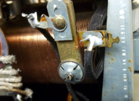
5. Unsolder the heavy yellow wire going to the metal Whistle Rectifier Bracket. Photo #11.
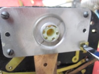
6. Using a pair of pliers gently bend the 4 aluminum tabs that hold the black top plate onto the bottom frame. Lift off the top black plate. Photo #12
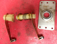
7. Flip the Top Plate over and remove the 4 screws holding the Retainer Plate on. Photo #13.
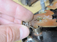
8. Carefully remove the Contact Arms, plastic Inner & Outer Shafts, Retaining Eyelets and Compression Spring. Photo #14
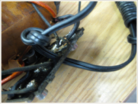
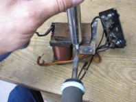
1. To remove the Core bend the 4 Aluminum Tabs straight that hold the Core into the bottom Coil Bracket. Photo # 15.
2. Gently lift the Core, Terminal Plate and Power Cord out of the Coil Bracket.
Disassembly - Cover and Controls
Disassembly - Top Plate & Rollers
Disassembly - Core, Terminal Plate & Power Cord


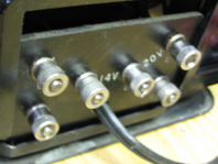
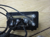
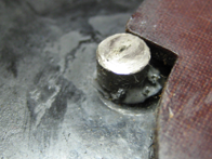
1. Twist the nuts tight on the 6 Binding Posts labeled A, B, C, D, U. Photo #16
2. If any of the nuts continue to turn after they have bottomed out then that Binding Post needs to be replaced.
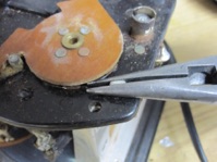
3. Remove the bad Binding Posts by grinding the back side of the Post off with a Dremel tool grinding disc. Be careful not to go too deep and ruin the wire connector. Photo #17
4. Grab the Post with pliers and twist, pull and rock it until the Post pulls out. If it doesn’t then do more grinding and try again.
5. Replace the Binding Post with part number T-159R threaded binding post and nut available at www.ttender.com. Photo #18
6. Insert the new Binding Post through the Terminal Board and through the wire connector on the other side. Add a lock washer and nut and tighten. Photo #19
7.Repeat for all of the loose Binding Posts.
Reassembly - Replace Broken Binding Posts

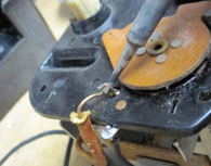
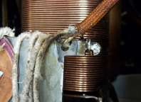
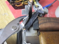
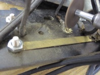
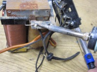
1. Remove the old power cord by unsoldering the 2 wires from the core. Photo #20
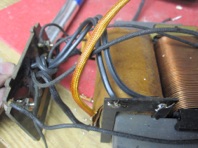
2. Us a desoldering tool or sucker to clean out the Core power terminal holes. Photo #21
3. Insert a new Power Cord (Part No. B-292) through the hole in the outside bottom of the Terminal Board. Photo #22
4. Tie a knot in the power cord on the core side of the Terminal Board about 4 inches from the end of the wires. Photo #23
5. Insert the striped ends of the power cord into the 2 terminal holes in the Core. Photo #23
6. Solder the 2 wires to the core. Photo # 24.

Reassembly - New Power Cord
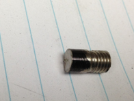
1. The Bakelite Top Plate has two 1/4” diameter round stops molded in to stop the Whistle Switches from turning too far. These tend to crack off disabling the Whistle Switch. Photo #24.
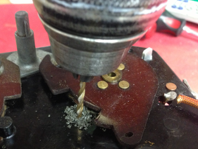
2. To replace the cracked off Whistle stop drill a 1/8” hole through the center of the cracked off stud. Photo #25
3. Drill the center of the 1/8” hole with a 7/32” drill. Photo #25
4. Use a 1/4-28 tap and thread the 7/32” hole. Photo #26
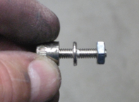
5. Find a 1/4-28 bolt with a shoulder between the threads and the bolt head and thread a 1/4-28 nut onto the threads tight against the shoulder. Photo #27
6.Use a Dremel reinforced cut off wheel and cut the remaining threads off the bolt up against the nut. Remove the nut. Photo #27
7. Put the head of the bolt in a vice and use the Dremel to cut the bolt head off leaving about 5/16” of shoulder next to the nut. Photo #28
8. Coat the threads with epoxy and thread the new Whistle Stop into the threaded hole. Replace the spring. Photos #29, #30, #31

Reassembly - Repair Broken Whistle Switch Stop


NOTE: The Carbon Rollers were originally press fit in a very expensive press which also required complete removal of the Roller Arm. If you can afford the press and tools this is the best method. Some people use special tools to accomplish the press fit with varying results. I choose to remove the arms completely then solder the Roller Pin to the brass arm. The result is electrically very good and if done right works every time. The trick is to clean the arm completely, use the correct flux, use plenty of heat and to verify that the rollers roll well after it cools off. This is how I do it. Please feel free to do it differently or use whatever method makes you feel good.
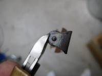
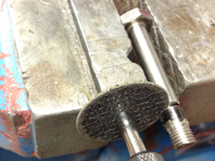
1. If the Carbon Rollers are worn out or have flat spots break the remaining Rollers out with a pair of wire cutters. Photos #32, 33.
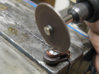
2. Use a Dremel cutting disc or wire cutters to cut the Roller Pin. Remove both ends of the pin. Photo #34
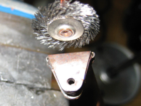
3. Use a wire wheel in a Dremel or grinder to gently polish the brass end of the Roller Arm. Photo #35
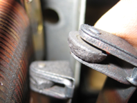
4. Install a new Carbon Roller (part V-45) and Roller Pin (part ZW-102) into the Roller Arm and then push down and clamp into a vice. Photo #36, #37
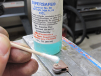
5. Add a drop of flux around the pin. Photo #37.
Use special water soluble flux like SuperSafe Flux by H & N Electronics. Do Not use Rosin Flux or it will harden and lock up the roller. If you use the wrong flux and it locks up soak the roller and arm in alcohol to dissolve the flux.
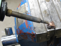
6. Heat up the end of the soldering iron to about 800 degrees, clean the tip with a wet sponge, apply some solder to the tip and then apply the tip to the side of the pin and to the brass Roller Arm. When the solder starts melting and flowing slowly rotate the soldering iron around the pin adding solder as needed until the pin is soldered all the way around. Photo #38
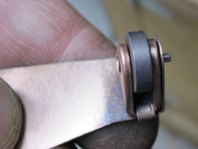
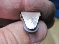
7. Use a Dremel with a grinding wheel to remove the excess solder and pin. Polish with a Dremel wire wheel. Photo #39, #40
8. After everything is cooled off make sure that the Carbon Roller spins nicely if not soak in alcohol, spin, soak again etc. until it spins nicely .

Reassembly - Replace Carbon Rollers